
In the world of Horology, there have been many different types of Escapement used for both clocks and watches, from the Verge and Foliot escapement used in 14th century tower clocks, to the 1990s Daniels co-axial escapement used in limited high-end watch brands. This essay will be a comparison and breakdown of two commonly used varieties, the Recoiling Anchor and the Detached Lever Escapement.
In layman’s terms, the escapement is the part of the clock or watch that makes the familiar “tick” and “tock” sounds. More specifically, the escapement is the beating heart of the timepiece, responsible for regulating the power given by the spring or weight in a useful way. In this circumstance, to keep accurate time with minimised variation. To do this, the escapement must periodically transmit impulses of the motive power (Pellaton, 1949), meaning take power from the mainspring and use it to power the regulator.
The Recoiling Anchor Escapement
When looking at pendulum clocks, a recoiling anchor escapement will be found fairly commonly. Invented in around 1657 by Robert Hooke (although some experts credit William Clement) (Roberts, 2007) the recoiling anchor uses a pendulum to regulate its timekeeping, giving it a small push (or, from here, Impulse) each swing in an attempt to make the swing of the pendulum consistent, thereby making the timekeeping accurate. As the pendulum swings through its arc it goes through 3 main stages; Impulse, drop, and recoil. When most people think of a pendulum, they assume that it is allowed to swing freely back and forth. However, if this were the case then the pendulum would stop fairly quickly due to losses in heat, friction and air resistance. This is why, in reality, pendulums are not allowed to swing freely for a lot of their swing, and are literally pushed around in order to keep them moving, and moving in a regular fashion.
The diagram below can be used to display the phases of the pendulum. All explanation from here will be in reference to the area labelled “Beat Period”, travelling between the pendulum’s two points of maximum displacement from the centre.
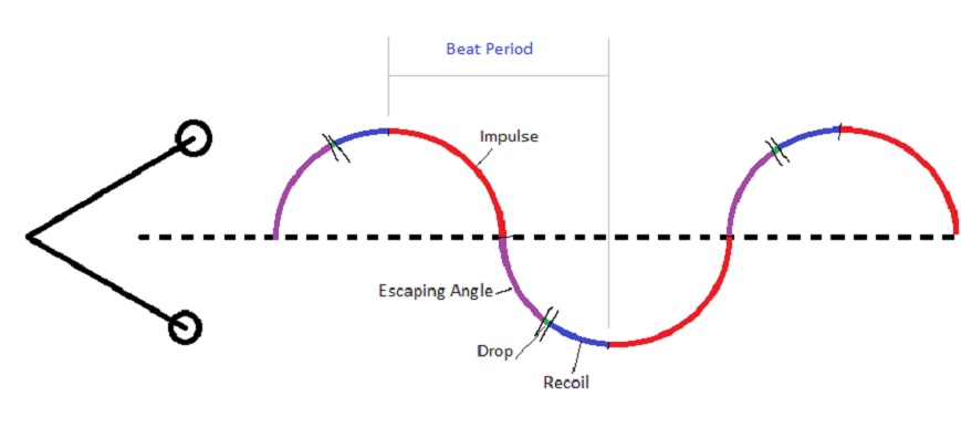
Impulse (Red section on diagram)
Below is a sketch showing the position of the escape wheel teeth relative to the pallets, assuming the pendulum is at maximum displacement to the right hand side, and the escape wheel is rotating clockwise.
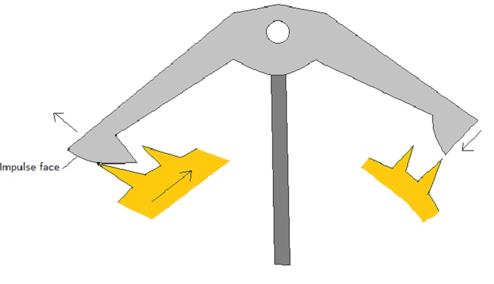
On the pallets, the two curved surfaces (one on each) are the Impulse faces. They are shaped in such a way so that when the pendulum is at maximum displacement and about to swing back in the other direction, the spring or weight giving power to the escape wheel slides the escape wheel teeth along the impulse face. As it moves towards the corner before dropping off, the pallet is effectively lifted up, and as the pendulum is connected to the pallet this has the effect of pushing the pendulum back in the opposite direction, as well as moving the other pallet into position to contact on the teeth on the other side.
Escaping Angle (Purple section)
The escaping angle could be included with impulse, but it is the angle that the pendulum swings through in the time between one tooth dropping and the following tooth on the other pallet escaping.
Drop (Green section between 2 black lines)
After the Impulse phase and the tooth has slid all the way along the impulse face, it drops off the pallet. There is a brief moment before a tooth on the other side touches on the other pallet, this is the only time where the pendulum is detached and allowed to swing freely.
Recoil (Blue section)
After drop, an escape wheel tooth will contact on the other pallet’s impulse face, locking the escape wheel in place. The momentum of the pendulum will keep the pallets moving, and after the escape wheel tooth has made contact, the wheel will be pushed backwards (anticlockwise) until the pendulum reaches the top of its swing (this is the supplementary arc), before starting to impulse again . This anticlockwise movement is the recoiling action that gives the escapement its name. When looking at an old pendulum clock, especially one with a seconds hand, it can be observed that the hands go backwards a tiny amount with each swing of the pendulum. This is a tell-tale sign that the clock has a recoiling anchor escapement.
The main criticisms of the recoiling anchor escapement were lack of isochronism, and the recoil itself. The recoiling action of the escapement puts additional wear on the pallets, and the backwards movement was thought to be a waste of energy that could be better used elsewhere. Isochronism is the idea that a pendulum’s ideal swing would be through a parabolic shape rather than a circular swing, and that this is best mimicked by making the amplitude of the pendulum as small as possible. From these ideas, Tompion and Graham worked on the Deadbeat escapement from around 1715 to 1751 (Roberts, 2007).
While the recoiling action and the lack of isochronism weren’t a problem in a household mantle clock for example, Tompion and Graham were seeking to make the most accurate clocks that they could. The Deadbeat escapements that were developed used a frictional rest where the pendulum was allowed to swing more freely, by having carefully manufactured escape wheels with extremely fine teeth, and pallets with “dead faces” on that didn’t recoil. The deadbeat escapement clocks also used extremely long pendulums with a heavy bob (and therefore a higher Q factor, discussed later) that had a very small amplitude, to increase isochronism.
Despite the invention of the deadbeat escapement, there is still a useful place for recoiling anchor escapements. They are easy to manufacture, and because of relative lack of precision (compared to the deadbeat and detached lever escapement) they can take a lot of punishment through winding and general wear and still work to an acceptable standard for a household.
The Detached Lever Escapement
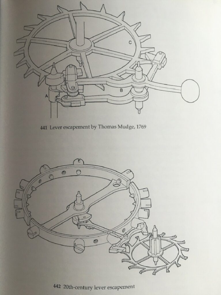
The Detached Lever Escapement was developed by Thomas Mudge in the 1754 (Daniels, 1981) century. It became a mainstay of British pocket watches where it replaced the Verge escapement. In Switzerland, Breguet and others developed the Swiss in-line club toothed lever escapement, which is still a standard in mechanical watches of today due to better all-round performance in retaining oil and impulse action.
The Swiss lever escapement works in a fairly similar way to the anchor escapement, but as pendulums cannot be used in watches another form of regulator was developed, in the form of the balance wheel. Instead of the pendulum swinging, the balance wheel spins to and fro, with a pin that delivers and receives impulse from the frame in which the pallets are mounted.
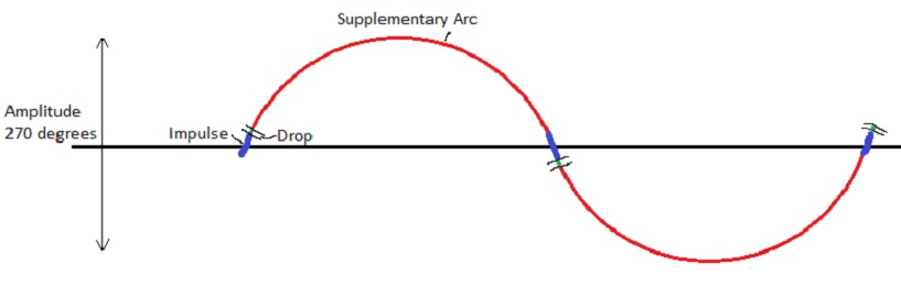
Similarly to the anchor escapement, the action of the lever escapement can be plotted on a graph, and broken down into 3 main phases. It still has impulse and drop, however there is no recoil in the lever escapement, so instead we have Lock. The escapement is slightly more complex than just those three phases though, as there are two types of lock, virtual and total, as well as a phenomenon called Draw, which also plays an important part in the working of the mechanism.
For this explanation, an idea of the shape of both the pallets and the escape wheel teeth is important. The sketch below labels the important parts, for reference.
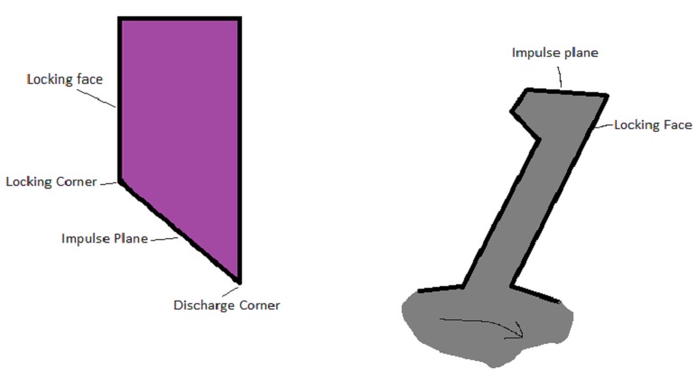
Assume that the cycle begins with the balance wheel at maximum amplitude clockwise, where momentum of the balance spinning has just been overcome by the potential energy stored in the spring and is just about to change direction and spin back towards the centre. The pallet frame will be fully over to the left hand side, stationary, and resting against the banking pin. The two locking faces on the diagram above will be in contact, in a state of Total lock. This is also a situation where Draw could be observed, if this arrangement was frozen in time and you tried to manually move the pallet frame away from the banking pin, the force from the escape wheel trying to rotate would resist the force, and push it back towards the banking pin (unless the escape wheel tooth slides past the locking corner of the pallet).
The balance wheel has a small pin attached to it, called the Impulse pin. This interacts with a notch at the top of the pallet frame, and is responsible for pushing the frame back and forth. As the balance wheel gets to maximum amplitude and then begins to go in the other direction, by the time the impulse pin reaches the notch it is travelling at its maximum speed, and therefore with maximum energy. This amount of energy is enough to push the pallet frame over enough to overcome the effect of Draw, and as with the anchor escapement described previously this lifts the pallet upwards, until the locking face of the tooth clears the locking corner of the pallet. At this point, the tooth will start sliding across the impulse plane, and the escape wheel wanting to rotate will push the pallet frame over until the tooth reaches the discharge corner of the pallet, and then drops. At the same time the pallet frame will be delivering impulse to the impulse pin via the notch, giving the balance wheel enough energy to reach maximum amplitude. As the pallet from was pushed over, the pallet on the other side comes into the path of the escape wheel teeth. As the tooth hits against the locking face of the pallet, it will be in a state of virtual lock, until the effects of draw push the frame over fully, up to the banking pin. This will now be in a state of total lock, and the cycle can begin again in the other direction.
The action of the escapement on the diagram below, with impulse only happening around the centre, and most of the time is spent in a state of lock, during the supplementary arc. This is why it is known as a detached escapement; for most of the cycle the balance wheel is free to rotate, and spends very little of its time in contact with the rest of the assembly. This is quite the opposite of the anchor escapement, where the pendulum is only allowed to act as a pendulum for a brief moment after drop.
A problem with the lever escapement, as in most mechanical systems, is friction, and overcoming it. Even though the jewelled pallets have a low co-efficient of friction, they still require oiling. Oil will thicken and harden over time, which can lead to inaccuracies as well as slowing down the train and effecting timekeeping. Companies such as Patek Phillipe are working to overcome this by developing escape wheels made of Silicon, that are hard and don’t require lubrication (Patek Phillipe, 2006).
Despite the need for lubrication and servicing more frequently than you might service a clock (a full strip, clean and re-oiling every 4 years as opposed to around 10 for a clock, which might only need oiling every 2), it is a remarkable achievement that a mechanical assembly that tells time as accurately as it does can be manufactured small enough to be worn on your wrist.
Appropriate Applications
Selection of escapement for an application is generally a question of how much power is available. Because the mainsprings are fairly large and powerful in clock applications, they can afford to have recoiling anchor escapements where a lot of power is used to keep the pendulum moving. Contrast this to a watch, where the mainspring is very small. Ignoring the logical reasons of why you couldn’t have a pendulum driven watch, there simply isn’t enough power available to keep one moving. This is why the balance wheel works for mechanical watches, it is lightweight and doesn’t require a huge amount of energy for impulse, and it is allowed to swing freely for the majority of its cycle.
The reason behind this is the “Q” factor. Q stands for quality, and is a measure of the quality of an oscillator. In horology, the oscillators are our pendulums and balance wheels, so they are available to be measured in this way. The Q factor gives you a bandwidth, or an area of variation in output that the mechanism operates within. The higher the Q, the lower the bandwidth, meaning that the escapement will be more accurate.
Specifically, Q is the ratio of restoring forces to dampening forces, or it can be written as Power/Loss. This explains why pendulum clocks work, they have a large mainspring and therefore a large amount of power, meaning that they can overcome the losses in the mechanism due to friction and energy used up during recoil, and can also afford to push around a big heavy pendulum bob. A pendulum in air typically has a Q value of ≤10000.
Mechanical Watches on the other hand have a much smaller typical Q value, of less than 100. This is the reason watch escapements are so carefully designed and have such tiny tolerances, they simply cannot afford to have any more losses in energy than are necessary. This is also the reason why watches use jewelled bearings, to reduce friction on all rotating surfaces due to the jewel’s low coefficient of friction compared to metal on metal.
It can be argued that Q is a less important aspect in overall accuracy than, for example, temperature compensation and making sure that pivots have minimal movement (Matthys, 2004), however there are still many arguments for and against the Q factor.
To conclude, it is somewhat unfair to compare the detached lever and the recoiling anchor escapement when their purposes are so different. The recoiling anchor is best compared to the deadbeat escapement, but there is still a place for the reliability and ease of manufacture of the recoil escapement. The swiss lever doesn’t really have a side by side comparison in the same way and a pendulum escapement couldn’t be used in a watch. For the purpose of wristwatches and the availability of parts the swiss lever is an excellent escapement overall, despite the relatively low Q factor compared to a pendulum. The development of the swiss lever brought with it many important innovations, most notably jewelled bearings.